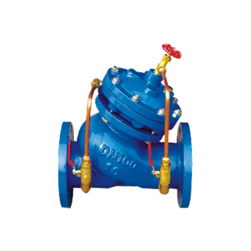
Check Valve Pressure Drop Calculation Methods
1. Introduction
Check valves are essential components in piping systems, designed to allow fluid flow in one direction while preventing backflow. Their primary function is to protect equipment, maintain system efficiency, and ensure safety. However, check valves introduce pressure drops (also called head loss) due to their internal design, which can impact system performance.
Calculating the pressure drop across a check valve is crucial for system design, pump selection, and energy efficiency optimization. This paper explores various methods for determining check valve pressure drop, including empirical formulas, manufacturer data, computational fluid dynamics (CFD), and experimental testing.
---
2. Fundamentals of Pressure Drop in Check Valves
2.1 Definition of Pressure Drop
Pressure drop (ΔP) is the difference in pressure between the inlet and outlet of a valve caused by flow resistance. It depends on:
- Flow rate (Q) – Higher flow rates increase turbulence and pressure loss.
- Valve type and design – Swing, lift, dual-plate, and ball check valves have different flow characteristics.
- Fluid properties – Density (ρ) and viscosity (μ) affect friction losses.
- Pipe diameter (D) – Smaller diameters increase velocity and pressure drop.
2.2 Key Parameters
- Flow coefficient (Cv or Kv) – Measures valve capacity (Cv is U.S. units, Kv is metric).
- Resistance coefficient (K) – Dimensionless factor representing valve-induced head loss.
- Reynolds number (Re) – Determines flow regime (laminar or turbulent).
---
3. Methods for Calculating Check Valve Pressure Drop
3.1 Empirical Formulas
3.1.1 Darcy-Weisbach Equation
The Darcy-Weisbach equation is widely used for pressure drop calculations in pipes and fittings, including valves:
\[
\Delta P = f \cdot \frac{L}{D} \cdot \frac{\rho v^2}{2}
\]
Where:
- \( f \) = friction factor (depends on Re and pipe roughness)
- \( L \) = equivalent length of the valve
- \( v \) = flow velocity
For valves, the equivalent length method converts valve resistance into an equivalent pipe length.
3.1.2 Resistance Coefficient (K) Method
The resistance coefficient (K) relates pressure drop directly to velocity head:
\[
\Delta P = K \cdot \frac{\rho v^2}{2}
\]
K values are typically provided by manufacturers or derived from experimental data.
3.1.3 Flow Coefficient (Cv or Kv) Method
The flow coefficient relates pressure drop to flow rate:
\[
C_v = Q \sqrt{\frac{SG}{\Delta P}}
\]
Where:
- \( Q \) = flow rate (GPM for Cv, m³/h for Kv)
- \( SG \) = specific gravity (relative to water)
Rearranged for pressure drop:
\[
\Delta P = SG \cdot \left( \frac{Q}{C_v} \right)^2
\]
3.2 Manufacturer Data and Standards
Valve manufacturers provide pressure drop curves or tables based on testing. Standards such as API 6D, ASME B16.34, and ISO 5208 define testing procedures for valve performance.
3.3 Computational Fluid Dynamics (CFD)
CFD simulations model fluid flow through a valve using numerical methods. Advantages include:
- Detailed visualization of flow patterns.
- Prediction of cavitation and turbulence effects.
- Optimization of valve geometry.
However, CFD requires expertise and computational resources.
3.4 Experimental Testing
Laboratory tests measure actual pressure drop under controlled conditions. Common methods include:
- Flow loop testing – Measures ΔP at varying flow rates.
- Differential pressure transducers – Record inlet and outlet pressures.
- PIV (Particle Image Velocimetry) – Visualizes flow behavior.
---
4. Factors Affecting Pressure Drop in Check Valves
4.1 Valve Type and Design
- Swing check valves – Low pressure drop when fully open but may cause turbulence.
- Lift check valves – Higher pressure drop due to restricted flow path.
- Dual-plate check valves – Compact design with moderate pressure drop.
- Ball check valves – Minimal pressure drop but limited to low-pressure applications.
4.2 Flow Conditions
- Steady vs. transient flow – Water hammer effects can increase pressure drop.
- Cavitation – Vapor bubble collapse increases localized pressure loss.
- Partially open conditions – Increases turbulence and head loss.
4.3 Installation Orientation
- Horizontal vs. vertical installation – Gravity affects disc movement and flow dynamics.
- Upstream/downstream piping – Poor alignment increases turbulence.
---
5. Practical Considerations for Engineers
5.1 Selecting the Right Check Valve
- Choose a valve with minimal pressure drop for energy efficiency.
- Consider system requirements (e.g., high-pressure vs. low-pressure applications).
5.2 Minimizing Pressure Drop
- Use full-bore valves where possible.
- Avoid unnecessary restrictions (e.g., reducers near the valve).
- Optimize pipe diameter to balance velocity and pressure loss.
5.3 System Modeling
- Use software tools (e.g., AFT Fathom, Pipe-Flo) to simulate pressure drop.
- Validate calculations with manufacturer data or testing.
---
6. Conclusion
Calculating check valve pressure drop is essential for efficient system design. Engineers can use empirical formulas (Darcy-Weisbach, K-factor, Cv), manufacturer data, CFD, or experimental testing. Each method has advantages and limitations, and the best approach depends on the application.
Understanding valve design, flow conditions, and installation factors helps optimize performance and reduce energy losses. Future advancements in CFD and smart valve technology may further improve pressure drop prediction accuracy.
---
References
1. Crane Co. (2013). Flow of Fluids Through Valves, Fittings, and Pipes (Technical Paper No. 410).
2. Idelchik, I. E. (2005). Handbook of Hydraulic Resistance. CRC Press.
3. API 6D (2022). Specification for Pipeline and Piping Valves.
4. ASME B16.34 (2020). Valves – Flanged, Threaded, and Welding End.
5. White, F. M. (2016). Fluid Mechanics (8th ed.). McGraw-Hill.
This paper provides a comprehensive overview of check valve pressure drop calculation methods, helping engineers make informed decisions in fluid system design.
Este sitio web utiliza cookies para garantizar que obtenga la mejor experiencia en nuestro sitio web.
Comentario
(0)